Segmented Circle Material in Unreal Engine 4
May 11, 2021

There are plenty of great tutorials out there that can help you create a circular material in Unreal Engine 4. For example, see Tom Looman's post on creating a circular progress bar with the help of a gradient texture, or a post from Unreal Possibilities showing how to do it without a texture. This post goes a bit further to show you how to chop a circle into segments.
I put this material to use in one of my latest demo projects, Rush Reborn. If you find this guide useful, you might want to check out that project as well.
Laying the Groundwork
The first thing we want to do is create a material and make sure our environment is set up so that it is easy to work with.
Create a Material
Right click anywhere in the Content Browser and create a material from the context menu that appears. I am calling my material M_Circle_Segmented, but call it whatever you want.
Set the Material Domain
Every material must be compiled for a specific target domain. You can switch the Material Domain in the Details panel of the material editor under the Material category. I am targeting the Deferred Decal domain, but the material should work just as well for User Interface and other domains.
We also need to set the Blend Mode (in the same category) to Translucent, because we use opacity to define our circle and its segments.
Using a Proper Canvas
You may find that your material is being previewed against a courtyard scene or some other colorful backdrop. This can make it tough to understand how the material looks while we are drafting it.
Instead, I prefer to work on a black background. To do so, navigate to the Window menu and open the Preview Scene Settings panel. In that window, find the Environment category and:
- Uncheck Show Environment
- Uncheck Show Floor
- Set Environment Color to black
On a similar note, the circle may be distorted when projected onto a sphere or cube. To remedy this, select the Plane option in the Viewport to preview the material on a flat surface.
A Note on Textures
The material that we will be building does not make use of any hand-designed textures. This is allows me to work around my general clumsiness with artsy softwares (Photoshop, Paint, etc.). It also serves the dual function of making our materials very flexible, which is great for prototyping. Materials that depend on textures can be harder to iterate on. Finally, because our material is entirely driven by math, it can be scaled up or down without losing fidelity.
Pick a Color
At this point, you should have a simple black material. That's rather boring (and possibly invisible against our black canvas). Adding color to our material is trivial.
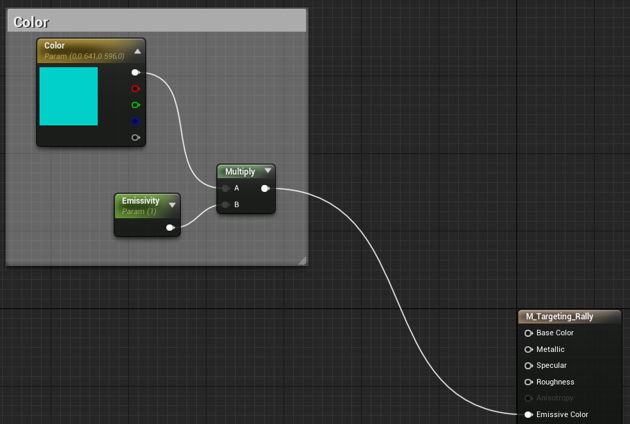
Simply add a Color vector parameter to control the color and an Emissivity scalar parameter to control the brightness. Multiply these parameters together, and plug the result into the Emissive Color field of the material. We now have the same flat output as before, but at least it's colorful.
Carving Out Circles
The remainder of our work lies in deciding which parts of the material should be visible. As you might expect, the results of the next steps are plugged into the Opacity field of the material, which dictates the parts of the material that are shown.
Our material will consist of two separate sections: a solid inner circle and a segmented outer circle.
Inner Circle
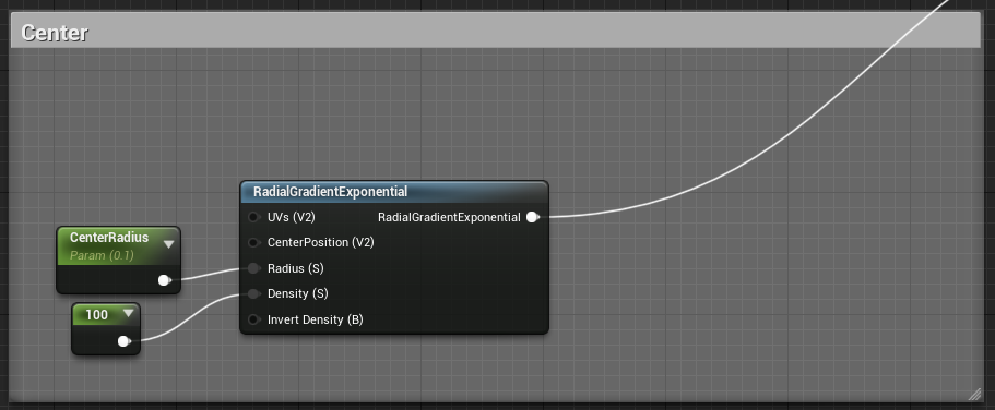
The inner circle is made using the RadialGradientExponential function. This function outputs a circle that starts at full density at its center and gradually decreases in density the further from the center you go.
We want our circle to be crisp and solid, so we plug in a high constant to the Density parameter. We also add a CenterRadius scalar parameter to control how large the inner circle is.
If we connect the result of the inner circle function to the Opacity material field, we should see just a small inner circle. Effectively, we are saying that wherever the input (the inner circle function) is greater than zero, show the material. Where the input is zero (black), hide the material. This understanding will come in handy very shortly.
Outer Circle
The segmented outer circle is a bit more involved, but it isn't too bad once you break it up into smaller pieces (pun intended).
Make a Solid Ring
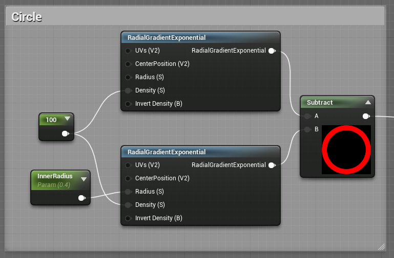
Start as if you were making a solid ring. Create two RadialGradientExponential functions, and set both of their Density parameters to a high constant.
Now make one of the circles a bit smaller by changing its Radius, and then subtract the smaller circle from the larger circle. This results in a solid ring.
Create Segments
To implement segments, we need to use a tiny bit of math. Create a Custom material function, which allows you to write inline shader code. Call it Segment.
In the Details panel for the node, add four inputs:
Origin- The normalized center of the circle (0.5, 0.5)Coordinate- The normalized texture coordinate (0-1)Segments- The number of segments to chop the circle intoGapSize- The size, in angles, between each segment
The Coordinate parameter should be supplied by a TexCoord node, which outputs where on a given material the current pixel is located. All other parameters should be set by constant or scalar parameter.
Then, in the Code field of the node, add the following:
float X = Coordinate.x - Origin.x;
float Y = Coordinate.y - Origin.y;

float Angle = (atan2(Y, X) * (180.f/PI)) + 180.f; // Angle 0-360
float SegmentSize = 360.f / Segments;
float NormalizedAngle = fmod(Angle, SegmentSize);

return (float)(NormalizedAngle > GapSize);
At the outset, we calculate the x, y positions of the current pixel coordinate relative to the origin. Then, we feed these positions to the atan2 function to determine the angle that the pixel sits at relative to the origin. The atan2 function is preferable to the standard arctangent, because the latter cannot return angles in all four quadrants. We then convert the atan2 output from radians to degrees and add 180 to get our angles into the range of 0-360, which is easier to work with.
Next, we determine the size of our segments in angles. For example, if we have twenty segments, each segment has a size of 18 degrees. We project our raw angle onto a single segment of SegmentSize using the fmod function to get the NormalizedAngle, which tells us where along the segment this pixel exists.
We return true (one/white/visible) if the NormalizedAngle is greater than the GapSize, and false (zero/black/hidden) otherwise. This way, pixels that fall into gaps are hidden and all others are shown.

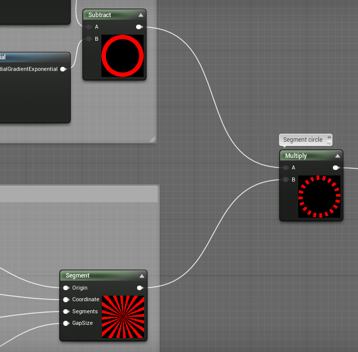
Combine the Ring and Segments
With the ring and the segments, we have created two separate opacity textures. By multiplying these textures together, we can produce a result that is visible only where both textures are visible (because multiplying zero by anything is zero). Et voila!
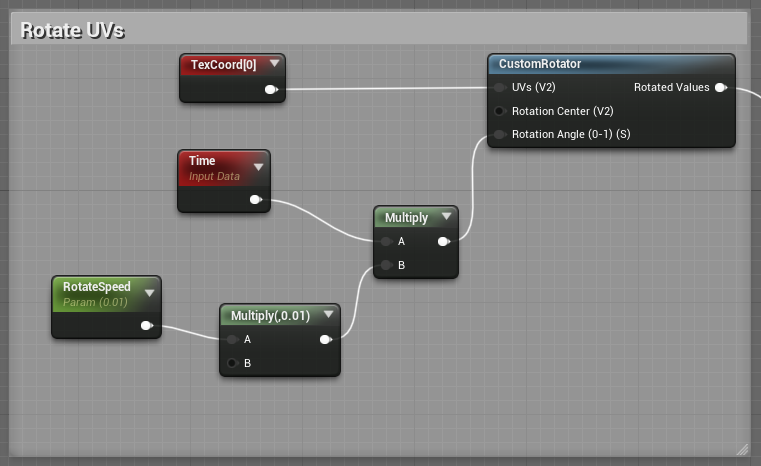
Extra Credit: Rotation
For completeness' sake, we should briefly cover how to rotate our segmented outer circle. As with most general rotations, use the CustomRotator function. Feed a TexCoord node into the UVs input and feed a Time node (slowed by some manipulations) into the Rotation Angle input.
Use the result of the rotation function in place of the TexCoord node as the Coordinate input for the Segment function.
Putting the Pieces Together
Add the inner and outer circles together, which results in visibility when either circle is visible. Pass that result into the Opacity material field.
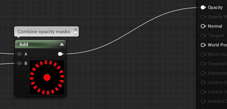
And there you have it. The final material should look something like this:
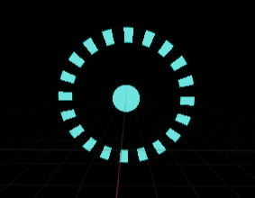
With a few tweaks to the parameters, this is what it looks like in Rush Reborn: